1. Introduction: The Importance of Wharf Buffer Systems for Berthing Safety
In modern ports and offshore facility construction, mooring posts and mooring grooves are key components that protect vessels and wharf structures from collision damage. With the expansion of global shipping, port upgrades, and the proliferation of large-tonnage vessels, buffer systems are now subject to higher demands in terms of performance, service life, maintainability, and intelligence. The old approach relying solely on empirical selection and excessive safety margins is being gradually replaced by new methods combining reliable modeling, structural optimization, sustainable materials, and smart monitoring.
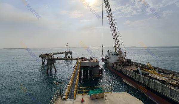
![cone-fender-for-dock]()
2. Fender Selection Principles: From “Can It Bear Load?” to “Performance Matching”
In the fender selection stage, one must follow a set of principles and standards to ensure the buffer system is neither over-conservative nor under-designed.
2.1 Standards and Reference Documents
(1)In China, JTJ 297-2001: Technical Specification for Wharf Auxiliary Facilities is a widely used reference, laying out definitions, fender types, spacing, load criteria, and design rules.
(2)Internationally, PIANC’s latest fender guidance (e.g. the WG 33 / PIANC Fender Guidelines) provides refined methods for berth energy calculation, berthing process simulation, and holistic design approach.
(3)For rubber fenders, industry norms such as HG/T 2866 and association standards (e.g. T/CANSI 31-2020) offer further guidance on selection and installation.
These standards provide foundational criteria (e.g. design energy absorption, maximum allowable compression, reaction force limits, etc.) and define design constraints (e.g. maximum face pressure, shear capacity, safety factors).
2.2 Berthing Energy Assessment and Buffer Demand
The core of selection is evaluating the effective collision energy that must be absorbed by the buffer system during vessel berthing:
(1)Based on vessel mass, approach velocity, draft, berthing direction misalignment, wharf structural stiffness, etc., compute the collision energy
(2)Account for environmental contributions: tide, currents, waves, wind-induced vessel motion that generate additional impacts
(3)Include safety margin: total absorption capacity of fenders should exceed design collision energy, considering performance degradation over service life
From the energy assessment, one can determine the appropriate fender type, dimensions, number, and layout.
2.3 Fender Types and Material Choices
Common fender types include:
(1) Solid rubber fenders (fixed / non-floating)
(2) Floating rubber fenders (e.g. pneumatic, filled types)
(3) Within rubber fenders: D-type, O-type, W-type, cone, arch, V-type, etc.
(4) Tire fenders / Tire combinations, often used in smaller ports
(5) Steel / metallic fenders or polyurethane / composite fenders, for high wear resistance, long life, or special applications
When selecting, one must compare overall performance in energy absorption / reaction force / pressure distribution / ease of installation / maintenance cost / service life.
For example, arch-type (or “arch” style) fenders often achieve greater energy absorption at lower reaction forces compared to simple V-type configurations under the same nominal compression.
2.4 Layout Strategy and Spacing Design
Even with a properly selected fender, poor layout can lead to buffer failure:
(1) Vertical multilayer arrangement / zoning by water level: In ports with large tidal range, deploy fenders at different vertical levels so that at varying water levels they still contact the hull
(2) Horizontal spacing: The gap between adjacent fenders must ensure that when fenders undergo design compression, no exposed sections of the wharf wall remain vulnerable
(3) Distribution along leading edge: Wharf types (quay wall, pile wharf, trestle wharf) demand differing layout strategies
(4) End / corner protection: End regions may require denser or reinforced fenders to handle local stress concentrations
(5) Overlapping / backup layouts: For a wide range of vessel sizes, consider overlapping or spare fenders to handle extreme berthing events
2.5 Safety Limits / Face Pressure / Shear Constraints
In fender design, one must strictly control:
(1) Maximum allowable face pressure: The pressure on the ship hull should not exceed allowable values
(2) Shear capacity: Especially under skewed or angled berth, the fender must resist shear forces
(3) Reaction force control: Reaction forces must not be too high to avoid damaging wharf or vessel structure
(4) Redundancy / safety factor: Factor in material degradation and extreme conditions so that the design retains margin
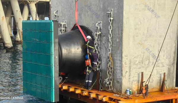
![cone-fender-installation]()
3. Structural Optimization Strategies: From Empirical to Simulation-Driven
Fender selection is only the first step. Structural optimization is more crucial to enhance performance, reduce cost, and extend service life.
3.1 System-Level Design Instead of Isolated Components
Modern design approaches emphasize considering the fender as part of a buffer system rather than treating the fender, anchoring structure, support frame, and foundation as isolated elements:
(1)The PIANC (WG 33) / newer guidelines emphasize that design should integrate fender, wharf structure, and mooring behavior rather than treating the fender in isolation
(2)For instance, the stiffness of the anchor structure, support connections, and embedded parts should match the buffering performance to avoid mismatch failures
3.2 Numerical Simulation / Nonlinear Analysis / Dynamic Coupled Calculations
With advances in simulation, designers may use finite element analysis (FEA), dynamic coupling models, contact-impact analysis, etc., to simulate the complex interactions among vessel hull, fender, and wharf structure.
For example, researchers have used nonlinear finite element models of the “hull–fender–wharf” system to simulate dynamic responses over the entire berthing sequence. Findings often show that as approach velocity increases, the fender’s absorption efficiency declines, leading to an upper bound on safe approach velocity (e.g. 2–2.5 knots in a given case).
Through such modeling, one can examine the time-series evolution of stresses, deformations, and absorbed energy throughout contact, compression, unloading, and rebound phases—then optimize fender profile, material distribution, and anchoring scheme.
3.3 Topology Optimization / Partitioned Optimization / Multi-Objective Optimization
Especially for large or high-performance fenders, one can consider:
(1) Topology optimization: Optimize internal structure or skeletal support to reduce weight and material while preserving performance
(2) Modular / unit-based design: Divide large fenders into modular units for easier fabrication, transport, and replacement
(3) Multi-objective optimization: Simultaneously optimize energy absorption, reaction force, cost, weight, and service life
3.4 Material Innovation and Durability Optimization
Material selection and durability are critical in structural optimization:
(1) High-performance rubber / composites / polymer-enhanced materials: reduce weight while improving fatigue resistance and aging performance
(2) Wear-resistant surface layers or liners: to mitigate localized wear
(3) Composite structures (e.g. metallic frame + elastomer covering): to balance stiffness and deformation capacity
(4) Sensor integration / self-diagnostic materials: to provide data for later monitoring
In design, one must account for environmental degradation (UV exposure, salt corrosion, temperature cycling, biofouling) which degrade material properties over time.
3.5 Anchoring Structures, Connection Modes, and Maintainability Design
Structures beyond the fender itself also have optimization potential:
(1) Anchoring methods (anchor rods, embedment, bolted joints, welding) must balance constructability and structural safety
(2) Connectors / support frames should have redundancy and ease of replacement
(3) Embedded parts / foundation must match wharf load-bearing capacity
(4) Ease of maintenance / replacement: design for corrosion protection, rapid removal, modular replacement
In the planning and design stage, provisions should be made for future maintenance and replacement to avoid “excellent fender but impossible to replace” pitfalls.
4. Current Design Trends in Wharf Buffer Systems
On top of selection and structural optimization, the following trends are emerging in modern buffer system design:
4.1 Modular, Custom, and Flexible Systems
With more diverse ranges of vessel sizes and berth conditions, the traditional “one-size-fits-all” fender is being replaced by modular and custom designs:
(1)Fender manufacturers are offering multiple modular units that can be assembled to match berth conditions
(2)Adjustable fenders or fenders with tunable stiffness or height
(3)Some providers now offer online selection tools integrated with fender + mooring post specification (e.g. Trelleborg’s design tools)
This trend enables designers to flexibly allocate buffer resources, reduce inventory cost, and adapt to future vessel changes.
4.2 Smart Monitoring, State Sensing, and Integrated Operation & Maintenance
Intelligence is a major direction in port infrastructure, and buffer systems are no exception:
(1)Embedding sensors (strain gauges, piezoelectric sensors, wireless pressure / displacement sensors, accelerometers) to monitor deformation, stress, and wear in real time
(2)Using IoT, cloud platforms, or digital twin technologies to link fender condition with port operation systems
(3)Using monitoring data to drive predictive maintenance, life estimation, and early warning
According to market research, the fender market is increasingly valuing sensor integration and condition-monitoring capabilities as a growth driver.
4.3 Green Design and Sustainable Materials
Under rising environmental and low-carbon demands, buffer system design is shifting toward greener, more sustainable directions:
(1)Use of durable, anti-aging, recyclable, or reusable materials
(2)Optimization to reduce material usage
(3)Environmentally friendly manufacturing processes to reduce carbon emissions
(4)Considering full life cycle costs (materials, maintenance, replacement) rather than just initial cost
4.4 Refined Design Through Berthing Behavior Simulation
Next-generation design relies more on fine-grained simulation and statistical analysis of berthing behavior:
(1) Use AIS / VTS (Automatic Identification System / Vessel Traffic Service) data to collect actual berth approach speeds, vessel type distributions, misalignment, offset angle, etc.
(2) Introduce uncertainty analysis (Monte Carlo, sensitivity analysis) into design
(3) Account for extreme conditions (storm, skewed berthing, high current berthing) and ensure buffer systems adapt
Such refined design helps avoid overdesign while ensuring safety under diverse scenarios.
4.5 Integration with Mooring Equipment / Unified Layout
Buffer systems no longer stand alone—they are being co-designed with mooring posts, mooring grooves, mooring rope layouts, etc.:
(1) Considering the influence of mooring line forces on buffer behavior
(2) Coordinating relative positions, stiffness, and load paths between fenders and mooring posts
(3) During berthing, mooring groove, rope guide devices, and buffer impact fields can interact and couple
This integrated view yields more reliable system performance and easier maintenance / operation.
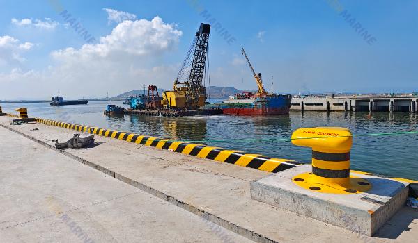
![yellow-T-bollard]()
5. Case Studies & Lessons Learned
Here are two illustrative cases or research studies and their insights for fender selection and structural optimization.
Case 1: Dynamic Coupled Simulation & Berthing Speed Limitation
In a study titled “Dynamic Simulation of Ship–Fender–Wharf Collision,” the authors build a nonlinear finite element model of the hull–fender–wharf system and simulate the full berthing sequence. The results indicate that as approach speed increases, fender absorption efficiency degrades; in the studied case, the maximum safe berthing speed was about 2.5 kn, with a recommended safe velocity of ~2.0 kn.
Implication: Even if fender selection is appropriate, if the actual berthing speed is too high, buffer performance may degrade or fail. Thus, speed control must be part of the design.
Case 2: Market Trend in Modularization & Smart Integration
According to market research, the fender market is shifting toward modular, customizable, and sensor-integrated solutions. Fender manufacturers are embedding condition-monitoring sensors, offering online design tools, and modular combination schemes to cater to varied port requirements.
Implication: In equipment manufacturing and system design, it is wise to reserve space for sensor layout, modular interface standards, and upgrade paths, in anticipation of future enhancements.
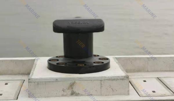
![black-T-bollard]()
6. Challenges and Recommendations
While progressing from fender selection to structural optimization, designers face several challenges:
1. Berthing behavior uncertainties
Approach velocity, misalignment angle, attitude, and vessel motion are highly random. Designs should incorporate statistical or Monte Carlo models to handle this uncertainty.
2. Material degradation and fatigue life prediction
Rubber and polymer materials degrade over time due to UV, salt spray, temperature cycling, biofouling, mechanical fatigue, etc. Lifespan prediction and margin design are essential.
3. Construction and installation constraints
Wharf embedded parts, anchor foundations, support frames must obey site constraints (depth, pile structure, wharf structural form). Design must ensure constructability.
4. System coupling complexity
Interaction among fenders, mooring posts, ropes, and grooves can be complicated. Joint simulation and iterative coupling models may be needed.
5. Balancing performance vs cost & maintenance
High-performance fenders with intelligent sensors are more expensive. Selection must trade off performance, cost, maintenance, and life cycle expenses.
6. Standards gaps and localization adaptation
While standards (e.g. JTJ, PIANC) exist, many projects must adapt to local climate, hydrology, vessel mix, and legal/regulatory constraints.
7. Conclusion and Outlook
From fender selection to structural optimization lies at the heart of wharf buffer system design. Looking ahead, buffer system design will rely increasingly on simulation tools, system-level thinking, material innovation, and intelligent monitoring. Modular customization, state sensing, and sustainable design are emerging directions. Meanwhile, designers must keep addressing uncertainties in berthing behavior, material aging, constructability constraints, system coupling, and whole-life cost concerns.
 English