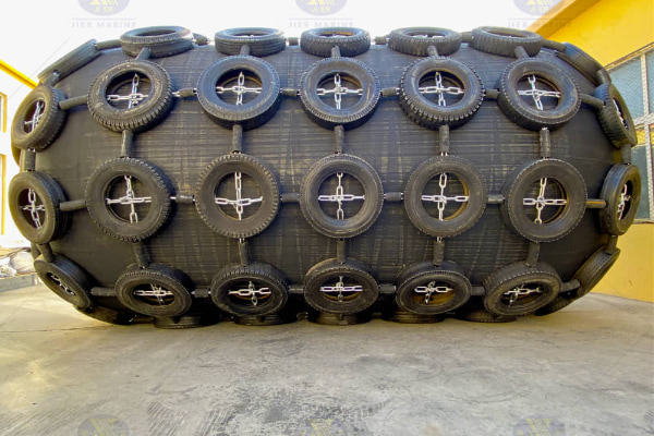
ISO 17357-2:2014 specifies requirements for low-pressure floating pneumatic rubber fenders (≤7 kPa initial pressure), including clamped end type (≤2.3m diameter) and moulded end type (≥2.8m diameter). It defines material specifications, performance criteria (guaranteed energy absorption at 60±5% deflection), dimensional tolerances, and essential tests (air leakage, durability, compression recovery). The standard ensures fenders safely absorb berthing energy while maintaining structural integrity in marine environments.
![Pneumatic-Fender]()
1. Low-pressure Fender Requirements
|
|
REQUIREMENT TYPE | DETAILS |
| Clamped end requirements | • Diameter ≤ 2.3m, cylindrical body with parabolic/parcel ends
• Multiple longitudinal vulcanized rubber-coated textile panels
• Inner/outer rubber coatings meet Table 2 requirements
• Coated textile panels meet Table 3 requirements
• Panels bonded with sufficient seam strength
• Ends sealed by clamped end fittings
• 1.8-2.3m: inflation fitting on sloping section
• <1.8m: single dual-purpose valve |
| Moulded end requirements | • Diameter ≥ 2.8m, cylindrical body with hemispherical ends
• Multiple longitudinal coated textile panels
• Inner/outer rubber coatings meet Table 2 requirements
• Coated textile panels meet Table 3 requirements
• Panels bonded with sufficient seam strength
• Hemispherical ends: high-tenacity weftless nylon cord reinforcement
• Reinforcement wraps around integral bead ring
• Moulded ends attached by circumferential seam
• Flange openings for end closure assembly |
| Size requirements | • Non-listed sizes must satisfy all requirements
• Use pressure requirements of next larger diameter size
• Example: 2.5m diameter uses 2.75m requirements |
2. Performance
|
|
PERFORMANCE INDICATOR | REQUIREMENTS |
| Performance specification | • Guaranteed Energy Absorption (GEA)
• Reaction force at GEA deflection (±10% tolerance)
• Hull pressure at GEA deflection |
| Performance curves | • Show relationship between deflection %, reaction force, internal pressure, and energy absorption
• From GEA value determine point A on curve
• Read corresponding deflection percentage (GEA deflection)
• Obtain reaction force and hull pressure at that deflection |
| Fender performance | • Moulded and clamped end fenders must satisfy Table 1 values
• GEA values obtained at (60±5)% deflection
• Reaction force tolerance at GEA deflection: ±10%
• Performance can be calculated using formula based on 8.1 performance test |
3. Prototype Fender Test Performance Confirmation
|
|
TEST TYPE | TEST REQUIREMENTS |
| General requirements | • Each unique construction/design requires prototype test
• Smaller diameter with same design/construction methods does not require test
• Manufacturer provides test certificate evaluated by major classification society
• Prototype test confirmation every 10 years |
| Performance test (parallel compression) | • Compress fender until energy absorption reaches GEA value
• Compression speed ≤ 80 mm/min
• Record reaction force and internal pressure every 5% deflection
• Repeat test twice with 5-min interval; use mean values
• Fender meets requirements if achieves 100% GEA without exceeding 65% deflection and 110% GEA reaction force
• Can use actual-size or >1/5 scale miniature fender |
| Angular compression test | • Determines fender deformation under angular loading
• Oversized fenders: miniature-size fender can be used
• Scale must ensure representative results
• One-fifth or larger scale is acceptable |
| Durability test | • Minimum 3,000 repetitive compression cycles from original diameter to maximum deflection
• No cracks or harmful defects after testing
• No reduction of GEA permitted
• Oversized fenders: miniature-size fender (>1/30 scale) can be used |
| Compression recovery test | • Compress to GEA deflection, hold for 1 min, release load
• Diameter must recover >97% of original diameter within 5 min
• Can use actual-size or >1/5 scale miniature fender |
| Puncture resistance test | • Specimen must use same coated textile as main fender body
• Conducted per ASTM D751 with specified screwdriver tip
• Minimum puncture force: 890 N |
| Recording conditions | • Ambient temperature and compression velocity must be recorded for all tests |
4. Test and Inspection for Commercial Fenders
|
|
| TEST TYPE | REQUIREMENTS |
| General requirements | • Acceptance testing based on specified tests and inspections
• Manufacturer must provide conformity certificate and test report
• Each fender must be marked with ISO standard number, pressure, size, etc. |
| Fender body material test | • Outer/inner rubber coating compounds tested per Table 2
• Test item 1: conducted on every compound batch
• Test item 2: for type approval of new rubber formulations
• Coated textile material tested per Table 3
• Test items 1-4: conducted on every production lot of coated textile |
| Dimensional inspection | • Conducted at initial internal pressure
• Length tolerance: +10%, -5%
• Diameter tolerance: +10%, -5%
• Diameter measured as average of at least two points at mid-cylinder section |
| Air leakage test | • Conducted on all fenders at initial pressure for 60 min
• Ideally performed in temperature-stable environment
• Maximum allowable pressure drop: 10 mbar
• Temperature compensation formula: P₂ = P₁ × T₂/T₁ |
| Hydrostatic pressure test | • 10-minute test at four times working pressure
• No water leakage or defects allowed
• Frequency: one per 20 fenders of each size (or per order if <20)
• Temporary elongation limits:
- Maximum circumferential: 15%
- Maximum longitudinal: 10% |
![dock fender]()
Table2 — Low-pressure fender rubber coating compound requirements
| Test | Specification | Test method |
| 1. Unaged |
|
|
| Hardness | 60-70 IRHD | ISO 48 |
| Tenslie strength | >14MPa | ISO 37 |
| Elongation at break | >300% | ISO 37 |
| Compression set(24 h, 40 ) | <40% | ISO 815-1 |
| 2. Static ozone ageing |
|
|
| 168 h, 20% extension, 50 pphma, 30 C | No visible cracks | ISO 1431-1 |
Table 3 — Low-pressure fenders coated textile requirements
| Test item | Test method | Required value |
| 1. Abrasion resistance | FED-STD-191 Method 5306H22 wheels, 1 000 gload | 25 000 cycles min to exposure of threads, out.side fabric only |
2. Breakingstrength (kN/50mm) Warp Weft | ISO 1421 | 875 min 1100 min |
3. Tear strength (N) Warp Weft | ISO 4674-1, Method B (single tear) | 1110 min 1110 min |
4. Surface coat adhesion (N/50mm) Outer cover Inner lining | ISO 2411 | 100 min 100 min |
 English